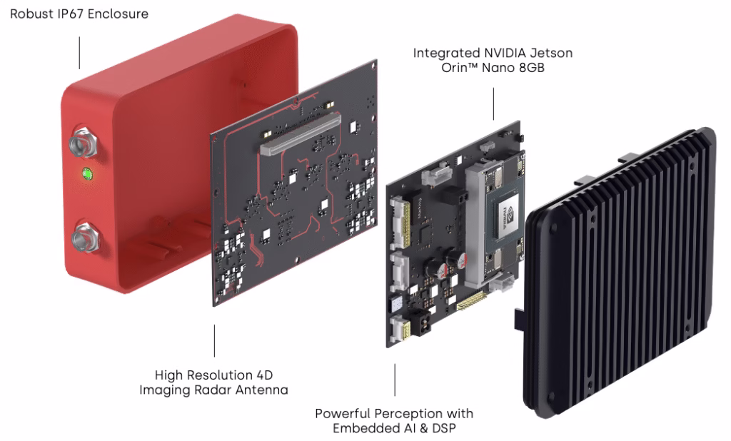
Delivering 5D Perception on-the-edge®: VizioR&I™ Imaging Radar with embedded NVIDIA Jetson Orin™ NX

Introduction

The VizioR&I™ platform from Provizio is not just another radar system; it represents a transformative leap in radar based perception technology. By integrating a robust mmWave radar sensor with an embedded GPU, VizioR&I™ delivers unparalleled performance while optimising size, weight, power, and cost in a single, scalable device. This innovation dramatically simplifies the perception challenge for OEMs, replacing complex, multi-component development stages and data processing steps with a single, streamlined solution.

VizioR&I™ Exploded View

The unique combination of proprietary hardware and software within VizioR&I™ provides unprecedented computational flexibility, enabling robust perception capabilities that surpass the state-of-the-art not just for radar, but also for LiDAR and camera technologies. The immense level of performance delivered by the embedded GPU, coupled with a streamlined plug & play design, make it an invaluable tool across various industries, from automotive and agriculture to mining and smart cities.

On-the-edge GPU

NVIDIA Jetson Orin™ NX delivers never before seen radar capabilities

Freespace Mapping

High performance radar-only freespace mapping for ADAS & AD applications

Odometry

Radar odometry enables GPS-free localisation in challenging environments

Robust low light & all weather performance

All Weather Reliability

VizioR&I™ provides robust performance in harsh conditions

Doppler Velocity

Intrinsic velocity measurement adds an additional layer of safety

Icon depicting VizioPrime spatial resolution as equivalent to that of LiDAR

High Spatial Resolution

On-device processing & proprietary software enhances radar point clouds

Why Perception On-The-Edge?

In the context of autonomous systems, perception refers to a machine's ability to interpret sensory data from its surroundings and make informed decisions. This involves detecting, classifying, and tracking objects, understanding spatial relationships, and anticipating potential hazards. However, developing a unified perception system that addresses all these tasks is a highly intricate and resource-intensive process.

With VizioR&I™, this heavy lifting has already been done. What would otherwise take months of painstaking work—developing, training, and fine-tuning perception models—can now be effortlessly replaced with our ready-to-use and fully optimised perception blocks. In essence, customers can simply plug-in the system and immediately benefit from advanced perception capabilities.

Radar-based 5D Perception on the left, Camera-based perception on the right

By eliminating the need to invest resources into understanding complex data and building customised models, VizioR&I™ provides a turnkey solution that allows customers to rapidly iterate & refine new innovations and application-specific enhancements. This not only reduces the time to market for new products, but also enables shifting developmental focus from the foundational aspects of perception to leveraging it in more strategic ways.

To contextualise the unique advantages of perception on-the-edge, let's examine the performance of VizioR&I™ across a variety of challenging perception scenarios.

Highway Obstacle Detection

VizioR&I™ Advantage

High resolution sensing with intrinsic Doppler velocity. Coupled with on-device perception, this provides effective detection & tracking of obstacles at range.

Embedded GPU Benefit

100 TOPS processing power from the NVIDIA Jetson Orin™ NX enables on-device data processing with minimal latency, delivering near instantaneous reaction times.

Localisation in GPS Denied Environments

VizioR&I™ Advantage

On-device localisation using radar point cloud based SLAM provides robust performance in adverse conditions & environments.

Embedded GPU Benefit

The high-speed 16GB LPDDR5 memory of the embedded GPU enables inter-frame point cloud position shift calculations in real-time.

Environmental Understanding

VizioR&I™ Advantage

Proprietary Neural Net (NN) algorithms provide high accuracy, low latency drivable free-space estimation using radar point cloud data.

Embedded GPU Benefit

The Deep Learning Accelerators (DLAs) and GPUs of the embedded NVIDIA Jetson Orin™ NX enable advanced on-device NN processing.

Robustness in Adverse Conditions

VizioR&I™ Advantage

mmWave radar technology provides more robust sensor performance in poor conditions. Advanced DSP & generative point cloud enhancements reduce noise and signal interference.

Embedded GPU Benefit

The 8-core ARM CPU & 32 Tensor core GPU of the embedded NVIDIA Jetson Orin™ NX enable simultaneous DSP and NN optimisation of the radar point cloud in real-time.

How Do We Do It?

Introducing 5D Perception®

5D Perception® running on VizioR&I™

Central to the notion of 5D Perception® is the synthesis of long-range, high-resolution 3D radar point clouds with Doppler velocity information, constituting the foundational four dimensions. By embedding perception capabilities directly on-the-edge through GPU-enabled radar processing, we introduce the fifth dimension, empowering VizioR&I™ to not merely detect objects, but to discern intricate details of their spatial context and movement dynamics. Using this technology, VizioR&I™ offers a unique take on the industry’s quest for robust & scalable perception by combining the sensor and perception platform into a single device, resulting in significant size, weight, power & cost benefits. Let’s take a closer look at how we achieve this.

DSP Point Cloud Enhancement

1. Initial Signal Processing:

Strong windowing is applied to reduce side-lobes, which are unwanted secondary peaks in the signal spectrum. This improves signal clarity, while also enabling the system to more quickly identify regions of interest with minimal computational load. After windowing, the time-domain radar signals are transformed into the frequency domain using a Fast Fourier Transform (FFT). This enables the identification of different frequency components corresponding to the range and velocity of targets.

2. 3D Domain Utilisation:

In the 2D range-Doppler domain, the Signal-to-Noise Ratio (SNR) span is narrower since detection thresholds need to be set low, thereby increasing the amount of unfiltered noise that passes through azimuth filtering. However, by utilising the 3D range-Doppler-Azimuth domain, the detection peaks are more pronounced, allowing for higher thresholds and reduced noise. In the image below, you can observe the enhanced clarity of detection peaks compared to a 2D and 1D FFT approach.

1D vs 2D vs 3D Azimuth Thresholding

3. Azimuth Response and Doppler Correction:

To obtain a valid azimuth response per range-Doppler bin, robust Doppler correction and demultiplexing are performed based on the modulation type used. The unique antenna array configuration of the VizioR&I™ sensor significantly enhances performance in this respect by ensuring optimal spatial sampling and reducing interference, leading to more accurate azimuth responses.

4. Zoom-in Processing:

After initial detection sectors are obtained, a propriatary Radar Resolution Enhancement Approach (RREA) is used to enhance the resolution within these sectors. RREA functions as a "zoom-in tool" by iteratively refining azimuth estimates within the detected sectors, increasing the resolution by 2x compared to the native resolution. The integration of RREA in the processing pipeline allows for improved azimuth estimation and the identification of hidden targets within radar captures.

Subsequently, by employing the above approach, a more intricate scene is produced with a resolution beyond the native setting and with significantly reduced noise, as exemplified in the images below:

VizioR&I™ point cloud denoising

Object Detection, Classification, and Tracking

Utilising our innate knowledge of the VizioR&I™ hardware, data processing system, and the point clouds it generates, we developed a novel approach in how we preprocess and encode our 4D radar data to maximise the performance of our downstream detection, classification & tracking systems. In addition, the NVIDIA Jetson Orin™ NX used in VizioR&I™ is equipped with NVIDIA's advanced Deep Learning Accelerators (DLAs) and GPUs, which are optimised for different types of neural network computations. Leveraging NVIDIA’s TensorRT software, our neural networks were designed to use this hardware in the most efficient way, resulting in superior performance over traditional algorithms for object detection, classification and tracking tasks, all without the need for any external compute resources.

As a result of these techniques, we observe the following benefits:

Additionally, VizioR&I™ offers long-range, proficient categorisation of detected objects into several distinct classes, including large vehicles, cars, pedestrians, motorbikes, cyclists, and traffic signs.

Vehicles detected and tracked above 300m with VizioR&I™ radar.
5D Perception, detecting cars, pedestrians and freespace, running on the edge in dense city areas.

Radar Odometry

VizioR&I™ applies a proprietary odometry algorithm that utilises the relationship between radar points and their relative velocity within a frame, combined with an analysis of between-frame position shifts, to calculate the ego vehicle’s velocity and yaw rate. This enables the accumulation of radar points over several seconds through dead-reckoning, which in-turn enables advanced localisation and mapping applications using radar data only. Internal benchmarking with GNSS reference data shows very accurate performance, with radar-based odometry being a viable alternative to GNSS-based localisation in challenging locations such as mines or urban canyons, where GNSS signals may not be available.

Radar odometry vs GNSS: Estimated yaw rate & velocity of ego-vehicle for a dual carriageway / urban environment point cloud capture.
VizioR&I™ precisely mapping streets.

Radar Free space

By leveraging the detailed point cloud, robust radar odometry data and embedded NVIDIA Jetson Orin™ NX within VizioR&I™, we can perform real-time, on-device radar free space mapping. As a complementary functionality to camera-based free space mapping, radar free space mapping can provide additional sensing range and enhanced robustness in harsh weather or environmental conditions. Moreover, the algorithm can provide robust free space mapping of indoor environments, such as parking garages, mines, and warehouses, due to its independence from GNSS signals.

In the figure below, we see an illustration of radar-only free space mapping performance:

Satellite view (left), freespace view (middle) and overlapping view (right)
Radar freespace running in real-time on VizioR&I™

For more information about our free space mapping algorithm visit: Accurately constructing free space maps using radar only - Provizio.

Working With VizioR&I™

Microservices Architecture

VizioR&I™ leverages a software-defined microservices architecture to share data for downstream services. Each microservice plays a crucial role in enhancing specific aspects of radar perception, and each can be updated independently. This allows for great flexibility in the distribution of computing resources, rapid prototyping of features, and a streamlined OTA update process.

Radar Microservices Architecture

Raw Radar Signal

The initial input obtained from the radar sensor, including reflections from various objects and surfaces in the environment.

Point Cloud

Processes the raw radar signal to generate a point cloud, which is a collection of data points in space representing the physical world as detected by the radar.

Radar-based Odometry

Estimates the position, velocity and orientation of the radar sensor by analysing changes in the radar point cloud over time.

SLAM Accumulation

Accumulates data over time to build a comprehensive map of the environment and provides accurate localisation within the mapped area.

Generative AI Enhanced Point Cloud

Uses generative AI techniques to enhance the raw point cloud data, improving its accuracy and resolution for downstream processes.

CNN Detection & Classification

Used to detect and identify different types of objects and their respective positions within the radar data, providing detailed insights into the environment.

Object Tracking

Uses data from CNN detection and classification, along with radar-based odometry, to maintain a continuous track of objects.

Freespace

Uses the accumulated SLAM data and object tracking information to determine areas free of obstacles, providing a clear path for navigation.

Sensor Fusion

Combines data from multiple sensors (including cameras or LiDAR) to create a more robust and comprehensive understanding of the environment.

Situational Awareness

Utilises fused sensor data to generate a complete situational awareness model. This model helps in making informed decisions by providing a holistic view of the environment, identifying potential hazards, and understanding the dynamic context of the scene.

Interfaces And APIs

VizioR&I™ is designed to be easy to use and integrate with existing systems across a wide variety of applications.

Communication Protocols

For communication, there is a choice between a simple UDP protocol or DDS to get ROS compatibility out-of-the-box.

Provizio APIs

VizioR&I™ offers APIs for communication and integration with various systems.

NVIDIA DRIVE Integration

VizioR&I™ is approved for use with the NVIDIA DRIVE AGX™ Platform, enabling customers to build and test ADAS solutions with maximum compatibility and flexibility within their existing R&D platforms. As the only radar platform on the market with a built-in NVIDIA Jetson Orin™ NX, VizioR&I™ offers customers never-before-seen radar perception capabilities that can be tailored to a wide variety of use cases.

Provizio GUI

The VizioR&I™ radar only needs power and a network connection before you can browse to its web interface and see the live point cloud output, or access radar configuration settings.

Foxglove

The Foxglove data visualisation platform is used by various companies to streamline debugging and accelerate development cycles in industries like autonomous vehicles and robotics research. VizioR&I™ offers native support for Foxglove using the MCAP format, enabling customers to easily visualise data captures and better understand the unique performance benefits of VizioR&I™ for their applications.

Multi-Sensor Compatibility

Each VizioR&I™ radar can be configured as a Precision Time Protocol (PTP) Master or PTP Slave on the local Ethernet network. This allows synchronisation of the radar with other sensors to within less than a microsecond accuracy, thereby enabling fusion of point clouds and/or images from multiple sensors for maximum perception performance.

Conclusion

In conclusion, VizioR&I™ is not just another radar system; it represents a quantum leap in radar technology. Until now, the seamless execution of multiple complex perception tasks & microservices required by an advanced perception platform like 5D Perception® would have required the use of high-power external processing systems and complex networking architectures. However, with the power of NVIDIA Jetson Orin™ NX, we have been able to consolidate all of these systems into a single device for the first time, enabling massive size, weight, power & cost optimisations compared to existing state-of-the-art solutions.

The unique combination of hardware and software within VizioR&I™ allows it to deliver high-resolution 3D point clouds, robust object detection and classification up to 300 meters, radar odometry, and radar free space mapping, far surpassing the performance and capabilities of existing market offerings. Additionally, our software-defined approach ensures continuous upgrades, extending the radar's useful life and enabling easy adaptability to new challenges and applications.

On-the-edge GPU

NVIDIA Jetson Orin™ NX delivers never before seen radar capabilities

Freespace Mapping

High performance radar-only freespace mapping for ADAS & AD applications

Odometry

Radar odometry enables GPS-free localisation in challenging environments

Robust low light & all weather performance

All Weather Reliability

VizioR&I™ provides robust performance in harsh conditions

Doppler Velocity

Intrinsic velocity measurement adds an additional layer of safety

Icon depicting VizioPrime spatial resolution as equivalent to that of LiDAR

High Spatial Resolution

On-device processing & proprietary software enhances radar point clouds

The immense level of innovation and performance built into VizioR&I™ make it an invaluable tool across various industries, from automotive and agriculture to mining and even smart cities. With its plug-and-play design, ease of integration, and compatibility with other sensors, VizioR&I™ is designed to meet the needs of any customer.

To experience the future of radar technology, we invite you to visit the VizioR&I™ webpage to learn more about our technology and stay updated on the availability of our VizioR&I™ unit. As Turing Award laureate Alan Kay wisely said, "The best way to predict the future is to invent it." With VizioR&I™, the future of mainstream radar perception has arrived.

Accurately constructing free space maps using radar free space mapping technology

Introduction

Preprocessed High Definition (HD) maps cannot capture changes in road structure, roadworks or debris. Therefore, onboard sensors must be able to estimate a real-time freespace map in order to avoid unexpected obstacles and navigate safely through an environment.

While radar has traditionally been used for object tracking because of its long-distance sensing and accurate doppler velocity measurement capabilities, the addition of our MIMSO® technology makes it a powerful sensor for gathering dense 3D pointclouds, and at a much lower cost than comparable sensors. The increased angular resolution capability of MIMSO® radars also enables complex perception tasks, like radar-only freespace estimation.

This whitepaper will explore our approach to radar free space mapping & estimation and how this compares to other freespace estimation techniques.

Definition of Freespace

Inverse Sensor Modelling (ISM) defines occupancy as either free, occupied, unobserved or partially observed [1], as seen in Figure 1. These labels are created by casting rays out from the sensor. Occupied represents any region with a sensor detection, free represents the area up to the first detection, partially observed is the region between the first and last detections, and unobserved is the region beyond the last detection.

We also include statically free and dynamically free labels to cater for the influence of static and dynamic object detections. This designation is made possible by our robust ego velocity estimation algorithm, which can estimate ground velocity and thereby remove detections that are not static i.e., dynamic targets. This allows us to create static and dynamic freespace maps, which highlight regions that will always be off limits and regions that might become traversable freespace in the near future.

Figure 1: An example scene with the ego vehicle and vehicle at range along a straight road with a junction. (Left) ISM’s ideal interpretation of freespace. (Right) Our ideal interpretation of freespace.

Technology Overview

Our 5D Perception® system is built upon an extensive microservice architecture. These microservices work together to produce perception outputs like freespace estimation. Figure 2 outlines how the data is processed in each microservice. The Odometry, Dynamic Target Filter and SLAM accumulation microservices prepare the radar pointcloud for freespace estimation as follows:

Figure 2: High-level radar microservices architecture diagram

Figure 3 illustrates the effectiveness of radar odometry for pointcloud accumulation. In the leftmost illustration, the road boundaries are very difficult to identify from a single pointcloud frame. In the middle figure, we see how accumulation significantly increases pointcloud density, thereby resulting in the structure of the road becoming clearly visible. Dynamic objects usually cause smearing with this type of accumulation because they are moving from frame to frame. However, this does not occur in our case because dynamic detections have been removed using our Dynamic Target Filter.

Figure 3: Pointcloud from a single frame (left), accumulated pointcloud using radar odometry (middle) and occupancy gridmap from accumulated pointcloud (right)

Once an accurate accumulated pointcloud has been produced by the microservice system, it is processed by the Freespace Estimation microservice, as described below and as illustrated in Figure 4.

Figure 4: Illustration of processing steps required for freespace estimation

The goal of our freespace estimation algorithm is to identify freespace beyond what can be seen by ray tracing. This makes it possible to estimate freespace that might be out of direct line-of-sight but that is still visible to the radar.

Comparing Freespace Performance

Radar compared to camera

Freespace estimation with camera has been extensively researched and many off-the-shelf road segmentation algorithms with decent performance already exist. Figure 5 below illustrates a comparison between our radar-only freespace algorithm and a camera-based road segmentation approach at a complex intersection. Road segmentation operates on the camera image and is then projected onto a plane in front of the camera to create a Bird’s-Eye-View (BEV). From the satellite image, we can clearly see that the freespace should be represented as the road diverging to the left to exit the roundabout, and the road that follows to the right around the roundabout.

Figure 5: Satellite view of roundabout scene with position and direction of vehicle (left). Comparison between the camera estimate BEV (middle) and our freespace estimate (right) at a diverging road

The camera freespace estimate follows the road very accurately and also provides road markings, which radar and some LiDAR cannot do. It is important to have an accurate model of the ground plane and camera intrinsics to project the camera estimate to a BEV. Small changes in pitch angle can cause large errors at long ranges. Radar does not have this issue because range is measured directly. Furthermore, our radar-only freespace estimate can ignore dynamic targets and produce an estimate of static freespace. This is challenging to do using camera because velocity is not directly measured.

Figure 6: Camera on a wet day with rain on the lens (left) and the freespace estimate from this image (right)

Figure 6 shows an example of rain reducing the accuracy of the freespace estimate. Water on the camera lens distorts and blocks the image, leading to an incorrect freespace estimate. Radar is not affected as severely by these weather conditions, which makes it a good complementary sensor to camera.

Radar compared to LiDAR

Inverse Sensor Modelling (ISM) is a common method for calculating freespace using LiDAR data. With this approach, a 3D pointcloud is converted to a 2D BEV representation and then passed to the algorithm. Freespace is marked between the sensor and the first detection along a ray. However, since a 2D BEV representation is used, there might be detail that is visible in 3D, but blocked/lost in the 2D view. As a result, curved and complex roads can have reduced freespace estimation range with this method.

The same roundabout scene from Figure 5 is shown in Figure 7. Our freespace algorithm follows the shape of the road in both directions to a range of 40m. However, the ISM freespace estimate using LiDAR data fails to follow the curvature of the road, which limits the range and accuracy of the estimate. Even though the side of the road is visible in the LiDAR data, ISM is being blocked by points closer to the sensor.

Figure 7: Satellite view of roundabout scene with position and direction of vehicle (left). Comparison between LiDAR estimate (middle) and our estimate (right) at a diverging road

Use Cases

The freespace algorithm showcased in this whitepaper, is a digital signal processing (DSP) algorithm and therefore can be run using a low power CPU. High performing GPUs are not needed in this case, unlike some of our deep learning approaches which can compliment this approach, as they are not always availible.

Unlike LiDAR pointclouds and camera images, radar pointclouds do not require ground segmentation. Reflections from the road are usually weak enough that they do not appear as a detection. LiDARs without velocity estimation and camera images also require dynamic target segmentation. As a result, pointcloud filtering with radar is simplified significantly because ground segmentation and dynamic target segmentation are not necessary. The low cost of this radar processing solution makes it a viable candidate for many industries such as automotive, mining and agriculture.

Curved roads and complex junctions

Figure 8 shows the same scenario as the comparison section above. A scene including curved roads and intersections with islands has been selected because many algorithms tend to fail in these situations. Satellite view, freespace view and the two views overlapping are shown in the figure. The overlapped view illustrates how the freespace estimate follows the shape of the roundabout and the shape of the diverging road.

Figure 8: Satellite view (left), freespace view (middle) and overlapping view (right)

Figure 8 contains a single example of freespace estimation in this environment. The video in Figure 9 contains more examples of freespace estimation around a roundabout. As can be seen in the video, freespace is quickly and consistently estimated as the vehicle approaches each junction.

Figure 9: Freespace estimation results (green), radar pointcloud (black) and camera view of challenging road layout scenario

Long range scenarios

Radar has excellent range capabilities, which allows obstacles to be detected early. Detection range is important for fast moving vehicles like cars and drones because large distances can be covered in a small amount of time. In Figure 10, we see an example of a truck pulled into the hard shoulder of a curved road. In the corresponding freespace map, we can see how the road visibly narrows next to the obstacle at 125m.

Figure 10: Truck circled in red on freespace map (left) and camera (right).

This scenario is difficult because the curve of the road obscures the obstacle. Despite this, the radar first detects the obstacle at greater than 300m and it is clearly visible in the freespace map at 125m as seen in Figure 11. The speed limit of the vehicle is 100km/h or 27.8m/s. Therefore the vehicle has 10.8 seconds from first detecting the object to process the obstacle and 4.5 seconds to avoid the vehicle using the freespace map.

Figure 11: Vehicle in hard shoulder at range on a curved road

Indoor scenarios

Indoor environments can be challenging to map because they are often dimly lit, cannot avail of GPS and have targets at both close and long range. These environments are particularly common in industrial use cases such as mining and warehouses. Since our approach uses radar-only to estimate the pose of the vehicle, it is not reliant on GPS or other external odometry methods.

Figure 12 shows an indoor car park environment which has harsh lighting, a variety of close and long range targets, and clutter above the radar. The clutter from the ceiling is removed correctly so that it does not block the freespace estimate. Using our technique, spaces between vehicles on the left and a junction to turn right are both detected at greater than 20m.

Figure 12: Free parking space detected beyond vehicles (orange) and right turn junction detected (blue)

Figure 12 is a snapshot from a longer video (shown in Figure 13), which illustrates freespace mapping performance when driving through an indoor car park. Freespace is estimated past a range of 30m, including free parking spaces, junctions, large open areas and dead-ends.

Figure 13: Indoor car park scene

Conclusion

Our radar free space mapping algorithm can be used in a variety of environments, including short range indoor and long range outdoor applications. It has also been shown that radar performs well in challenging lighting and weather conditions, which makes it a good complementary sensor to camera. The low cost of the radar and processing stack makes radar-only freespace a viable option for industries such as automotive, mining and agriculture.

Our radar free space mapping algorithm can function using just one radar or by combining multiple radar pointclouds together. Odometry is calculated using the radar pointcloud and used to accumulate the pointcloud to provide greater density. This is possible because of the accurate doppler velocity estimate that radar provides and our robust ego velocity estimation algorithm.

Estimate accuracy and range is improved by looking beyond line-of-sight. This allows us to predict where the road will become free in the future, well before the vehicle arrives at that location. Many freespace algorithms fail around curved and complex road structures but our estimate does not degrade in these conditions. Furthermore, dynamic objects are easily removed, which allows us to provide a separate static freespace estimate and dynamic freespace estimate.

References

[1] Probably Unknown: Deep Inverse Sensor Modelling In Radar: https://arxiv.org/pdf/1810.08151.pdf

How Our Perception Improved in Just One Week at CES 2024

Introduction

In the dynamic landscape of radar technology, the advent of software-defined radars has revolutionised the industry. This shift has allowed for the continuous enhancement of radar capabilities through over-the-air (OTA) updates. At the forefront of this evolution is Provizio, pioneering advancements in imaging radar perception. This white paper delves into the capabilities of our software defined radar systems by highlighting the improvements achieved to our perception stack through optimisation and fine-tuning in just a couple of days at CES 2024.

Technology Overview

Software Defined Radar Microservice Architecture

Traditionally, radar systems were static in their capabilities, limited by their hardware configurations. The emergance of software-defined radars has changed this paradigm, enabling continuous enhancements and updates to meet evolving requirements. In addition to using software-defined radar, our 5D Perception® system is built upon a sophisticated microservice architecture. Each microservice plays a crucial role in enhancing specific aspects of radar perception, and each can be updated independently, resulting in an agile and responsive system.

To simplify communication between different microservices, a system called DDS (Data Distribution Service) is used. DDS is a networking middleware that simplifies complex network programming by implementing a publish-subscribe pattern for sending and receiving data, events, and commands among the nodes. Publishers create topics such as odometry, classification, and freespace to publish data, and DDS then delivers the data to subscribers who declare an interest in those topics. Below is a description of some of the main perception topics implemented in our 5D Perception® system.

The radar microservice architecture

Detection, Classification & Tracking

Utilising a state-of-the-art neural network optimised for Nvidia Orin, our 5D Perception® system excels in object detection, classification, and tracking. The microservice incorporates many steps, including:

CES Optimisations

Fine Tuning our Neural Networks

To optimise the detection and classification capabilities of our radar, we used our demo drives at CES 2024 to further fine-tune the neural network.

Our general dataset is made of a balanced distribution of captures taken in multiple environments, including large & small cities, motorways, countryside, car-parks, etc. from Europe and the US. At the time of CES 2024, we already had a Las Vegas dataset from our previous attendance at CES 2023, representing ~10% of this general dataset.

Object proportion, per capture type, in the detection & classification dataset

Using captures taken in Las Vegas during CES 2024, our engineers created a new dataset by combining 50% of the data from our general balanced dataset and 50% from new data captured in Las Vegas. Using our pre-trained general model covering various scenarios, a targeted fine-tuning session was initiated on our NVIDIA DGX A100 training computer.

An illustration of radar data flow from one layer to the next in the Neural Network

Benchmarking Improvements to Classification & Tracking

To benchmark the performance of the system, we used a capture of roads from Las Vegas (which had not been used for training the model), to validate that our model demonstrated improved performance. In this respect, two key metrics were used:

Note that precision is not as important as recall, as tracking largely tends to remove false positives due to the fact that an entity like a car is being tracked only after at least 2 frames of being detected. Thus, the false cars or pedestrians being detected during only 1 frame are not considered by our tracking microservice.

The benchmark is made of 750 labelled entities along 250 frames of pure Las Vegas streets and roads, representing both day and night-time lighting conditions.

These benchmarks revealed an increase of nearly 9% in precision and recall for cars and up to 6% in recall and 5% in precision for large-vehicles on the new fine-tuned CES 2024 model. While it may appear small, going from 0.715 to 0.778 in recall is a massive performance improvement for our model. In fact, the fine-tuned model achieved state-of-the-art performance in our internal radar detection and classification benchmark.

In the comparison below, we can see that cars are detected up to 20m further away (in medium range mode, < 100m) in the CES 2024 fine-tuned model, when compared with the previous model. This improvement also results in the system being able to evaluate the trajectory of vehicles on up to 10 more frames, producing 35% less false negatives.

Comparison between our general model on the left and the CES fine-tuned model on the right.

Finally, the late-tracking system in the neural network was enhanced by making a slight adjustment to the tracking_buffer hyperparameter. It was discovered that increasing the buffer from 20 frames to 30 frames resulted in an improved stability of 45% in pedestrian tracking and 25% in cars and large-vehicle tracking. For context, the tracking stability is defined by how much time an object is detected compared to its actual appearance in the field of view of the radar. This change allows detected objects to reappear in the radar field of view after up to 30 frames, which is equivalent to 3 seconds for a radar operating at 10Hz.

Freespace Optimisations

The Freespace microservice is dedicated to identifying open driving areas on the radar. Using only the point cloud data, this service seeks out the location of kerbs and pavements, as well as highlighting unidentified objects in the middle of the road, in order to give meaningful insight to achieve local freespace pathfinding. Amazingly, the efficiency of the system allows us to achieve this at a rate of 20 FPS, without the need for a powerful in-cab server.

The Freespace microservice attempts to identify the optimal path using only the radar point cloud.

As we are constantly improving the microservice, the new captures taken at CES 2024 allowed us to publish a version that accounts better for variations in infrastructure (e.g., different road sizes and layouts) between Europe and the USA, resulting in a more versatile and robust system. Since the Freespace microservice relies primarily on data from point-cloud clustering, ransac road boundaries estimation and odometry, the fine-tuning process consisted of finding the perfect balance between raising the clustering threshold while maintaining reliable road boundaries estimation.

As a result of these optimisations, the medium range (100m) freespace detection distance for Las-Vegas boulevards and large interstate roads went from an average maximum range of 53m to an optimised maximum range of 86m. This is a 62% increase in average maximum range for the detection of freespace - day and night, in all weather conditions.

Freespace is highlighted to indicate boundaries while avoiding other cars on the road.

Conclusion

By leveraging the power of software-defined radars and OTA updates, we are able to perform near real-time optimisation of our perception system to provide higher performance in a variety of areas - from classification & tracking, to radar-based odometry and freespace detection at CES 2024.

Using a refined technique and measurements taken over only a few days, our system demonstrated:

Furthermore, these updates were delivered rapidly through the use of an in-house data processing pipeline, which uploaded the latest captures to the cloud, extracted and pre-processed the data, and then used the data for fine-tuning of our neural network models. In this way, our models could be seamlessly optimised overnight, delivering improved performance for the next day of captures and demos.

This is just a glimpse of the future of radar technology, where software systems working on-the-edge are constantly learning and adapting. We believe that making the transition to scalable L3+ a reality is a challenge that can be solved by continuously learning and improving our solution, enabled by technologies such as those outlined in this paper.